
- A 9V battery must connect to the battery + of the voltage regulator andground of the voltage regulator.
- The 4.8V from the battery holder must connect to the ground of the black capacitor and the servo power bus.
- DO NOT connect the battery + end of the capacitor to the battery + end of 4.8V battery!!!!
Transistioning between mechanical construction and electronics, we need to setup the batteries. There are two ways I will show you how to do this. The first way I will show you, and also the better yet more expensive method, is by using a 6V RC battery pack. This is the same battery pack I used in Step 2 to test as a remote control robot.
 You can probably locate a pack like this from a remote control car you own, buy online for ~$10, or make your own by putting 5 AA batteries in series. For small robots I recommend NiHM type batteries at 1500mAh and above. If you are serious about robotics, put in the money and buy a battery pack! Its a good investment (I own like 4 of this type of battery, not including all the other types I got). You should also consider getting an ON/OFF switch for your battery pack, although it isnt really required (you could just unplug your battery). I got this one for ~$2. Plug your battery into one end, and the other end can go to the battery connection on your robot. Also, notice the velcro on the bottom of the battery. I will talk about this in the following section.
  Now just place the battery pack on the velcro already on your robot. You could also use long cable ties or tape, but I don't recommend it. What I like about the water bottle on the robot is that I can put stuff into it - batteries, sensors, baby squirrels, etc. You could also mount a small box on top of your robot to store the batteries. As a matter of fact, the Olimex programmer you bought for this project comes in a box that is just the right size. You are only limited by your imagination and what you have available to scrap.
  And you're done! (with batteries) For more battery information, check out the batteries tutorial.
 But suppose you don't have the money or don't want to buy a battery pack. There is another way.The other battery method is to get a battery holder, use the AA's that you have in your digital camera to power servos, and a 9V battery to power the AVR microcontroller. These are three different types of battery holders I own, but the middle one is best because its encased and has a built-in ON/OFF switch. All three can be bought from RadioShack (buy the middle one!!!).

Opening the battery holder up, I put four AA NiMH type batteries into it. Make sure you use rechargeable batteries, as they last much longer and supply much better power to your robot servos (thereby making Al Gore happy). You need four batteries.If you dont own AA batteries (cause you're weird or something), you can buy them for like $5 at any convenience store. Get the ones with the highest number for mAh and that say NiMH. Buy a charger if you don't already own one, too - or continue reading later on how to make your own battery charger. I assume you have batteries already cause most people own a digital camera (so I didnt include it in the $50).

I like to use velcro to attach batteries to small and medium sized robots. This allows me to easily remove batteries for recharging, or to quickly put on other robots I've made that share the same battery pack.Cut a small sheet of velcro into a square as shown.
 Remove the protective backing from the velcro and stick the velcro on to the bottom of your battery pack. I realize at least one person out there is going to make the dumb mistake of covering up the screw with the velcro - don't do that! =P
Then just simply attach the velcro to the velcro already on the robot.
 If you don't have velcro, you can also drill a small hole inside the plastic, and put a screw through it. Then drill another hole in your robot, and pass the same screw through that hole too. Lastly, use a nut to tighten the screw on. This is a demonstration of me doing it, although I didn't actually drill a hole (pretend, please!).
  If you plan to build many robots in the future, I recommend going out to buy a 25 foot roll of velcro for like ~$20. I use it all the time for attaching batteries, and it will last you like 5+ years. Definitely a good investment.
 Before we continue, I want to show you a cheap way to recharge your batteries. Search around for a power supply in your house that you are no longer using. They are fairly easy to find and/or scrap.
 Make sure it outputs the same voltage as your batteries. For example, if you have a 6V RC battery pack, make sure the power supply says 6V. If you put four battery cells together, make sure it says 4.8V (because 4 cells at 1.2V each equals 4.8V). Make sure it outputs a low current (trickle charge). 100mA seems to work fine for me. If the output current is too high, your batteries could overheat and as a consequence become damaged (or start a fire). Typical recharge times will be about 10+ hours. The more professional chargers out there that you can buy could take significantly less time, as they are designed to charge as fast as possible without damaging the battery. These chargers range from $10 to $60, dependent on features.
  Now cut off the adaptor end of the long wire. There are two ways you can attach it to your battery. You could use aligator clips to connect the power supply to your battery pack wires (make sure ground and power aren't reversed). The method I used is to attach a male header to the wires so it goes right into the RC pack plug. I will talk more about male headers towards the end of this page.
 Now lets go over the components you will need for your first robot. If you would like to learn more about basic electronics, have a look at the electronics basics tutorial.This is a 5 pack of photoresistors I bought from RadioShack. This variety is great, cause now I can choose the 2 photoresistors I like best (aka, give the best sensor readings). For more information on photoresistors, read the photoresistor tutorial.

This is a prototyping board (known by RadioShack as a 'Component PC Board,' wherever they got that from . . .). To use it, stick your components into the board and solder them in according to the schematic, as I will soon show. These boards are also known as 'perf boards', short for perforated boards (has lots of holes in it).
 You can also get what is called a breadboard. It works in a similar way to a prototyping board, but none of the connections are permanent. The benefits are that it doesn't require any soldering, and that you can quickly change your circuit as you please (great for experimenting!). The one shown here is a mini-breadboard, small enough to fit on your robot, and it has a sticky backing that you can stick right on to your robot with no effort.
  There are two disadvantages to the breadboard: they can be a little costly, and the connections aren't as secure as with a prototyping board. I wont be using the mini-bread board for this project, but if you plan to build more robots in the future, I suggest you to make an investment =P
 These are the parts I got from the DigiKey Order. Note the two grayish bags labeled 'Static Shielding Bag' on the bright yellow warning labels. This basically means that the components inside these bags are static sensitive, so be careful. Keep these bags, as they could be useful for your future electronics projects, or at least a good storage place for sensitive electronics.

Your battery is never a fixed voltage. Just because it says 6V doesn't mean it couldn't be 7V or 5V. This voltage always changes, and can cause havoc on your microcontroller and sensors. To correct for this, you need a 5V voltage regulator. What this does is ensures 5V will always be supplied to your sensitive electronics.
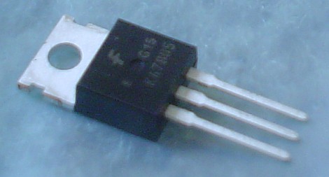 The voltage regulator will have three pins: Unregulated Input, Ground, and Regulated output.
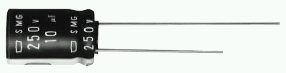
 The large capacitor is not entirely necessary, but is good to help reduce electric noise and keep the system powered during sudden power drains. Even a short lived sudden drop in power could reset your robot microcontroller (bad). The value of this capacitor doesn't really matter, but 100uF and above is a good starting point. More servos you use, the higher you want it to be. It should also always be rated twice that of your input voltage. Your input voltage is ~6V, so you would want it rated for 10V or 15V.
A second 0.1uF capacitor must go between GND and AVCC, as close to the microcontroller pins as you can make it. This capacitor is required to create a low pass filter for the analog-to-digital (ADC) converter.If you ever do high precision ADC measurements (unlikely), put a 0.1 uF cap in between AREF and ground as well. The point behind having the AREF pin is so you can feed it an input from a super-stable voltage source, and it will scale the ADC inputs from ground up to AREF with the full 10 bits of precision. Of course, you need to make sure none of your analog inputs go over AREF if you are using it like that.

The LED will be used as a status indicator. The LED is useful for knowing if your microcontroller is powered properly, and can output other useful information for testing purposes. A resistor wired in series is required so keep the LED from frying. Any resistor value from 10 ohm to 1 kohm will probably work. Higher resistance values reduce the power drain (good), but also decrease brightness (bad).
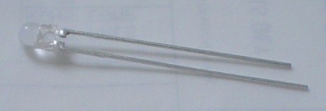 Note that the two wires on the LED are different lengths. The longer wire is always + and the shorter is -. The LED is polarized, meaning they will only work if current goes the correct way. If you connect it in reverse, they will either fry, or just simply not work.
 The long black thing with pointy metal pins sticking out of it is called a male breakaway header. These things, useful for plugging in servos and sensors, can be easily broken to your custom length requirements.
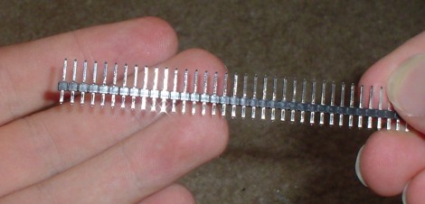 To break them, you can either use your hands, or a pair of sharp snips or scissors also works. Break three of length 6, five of length 5, and one of length 3.
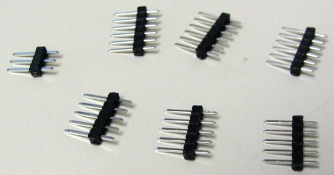
Now you need a schematic. A schematic is a wiring diagram that tells you where to attach wires to all the parts in your circuit. A schematic, to the uninitiated, can be a little overwhelming at first.So instead of possibly confusing you, I invented what I call a colored dot schematic. I'm willing to bet a 3 year old can understand this enough to build the circuit . . . (apologies to all 3 year olds reading this tutorial) Click the below image to open up an enlarged version. As you can see, I color coded each of the pins to determine which wire goes where. For example, all red dots should be connected to the + of your battery, and all purple dots should be connected together. If you're saying, 'gasp! I'm color blind!' Well, I numbered/labeled the pins too. Ill assume you know how to connect the dots, so I wont go into much detail into which wire goes where. =P
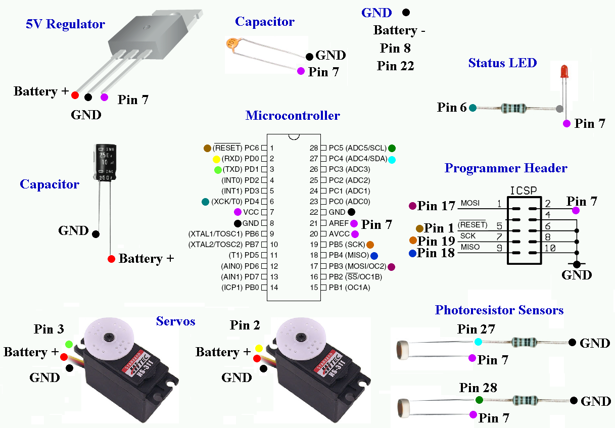 Note: If you are a dot-o-phobe, you can find a visual $50 Robot schematic on this forum post. Now I must point out that this schematic (and the following tutorial instructions) is for if you decided to use an RC battery pack (or an assembly of batteries equal to 6V or greater). But if you went with the battery holder method, you must make the following changes:
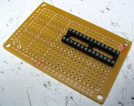
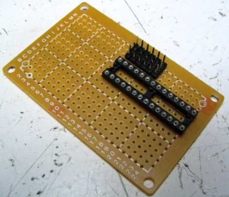
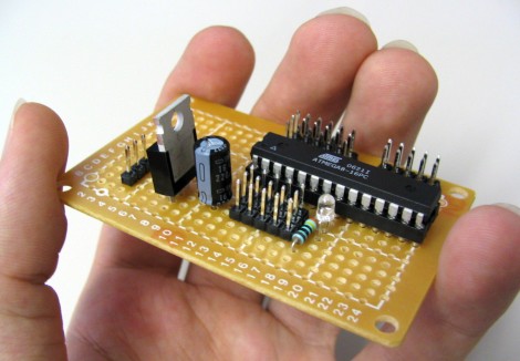
 As shown, place the DIP socket into your perf board. DO NOT add the microcontroller IC to the socket yet.It is not required, but I recommend copying the placement of all my components. If you look on the perf board, you will notice a number and letter grid system. This should be used as a guide to help you.
 Turn the board over and solder it in. To do so, heat up the pin for about a second or two, then add the solder second. Make sure each and every pin is soldered. Also, make sure the side you are soldering has the copper padding - this makes it much easier!
 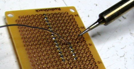 If you don't own a soldering iron, you can get a cheap one for around ~$10. RadioShack also sells them. If you want to make an investment, get a soldering iron that you can adjust the temperature on, and get nice tips. Remember, if you overheat the iron and apply pressure on the tip, the tip will dull and bend.
 Place three of the 6 pin male headers as shown. These pins will be used in the future to plug in your robot sensors.
 Then turn it over and solder each pin in.
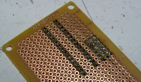
In this step we will add more headers and a resistor (do one at a time!). I designed the programmer header for an older programmer version, so chances are you will need to convert it to the new 6 pin header. It is easier to wire, it just requires a bit more of thought. Just check the number of pins on your programmer cable to know if you need 6 pins or 10 pins.
 First add the three 5 pin male headers and solder them in. Also, I want you to connect all the pins as you see in the image (or schematic). For the pins closest to the DIP socket, connect each one individually. For the outer rows, connect them in parallel, as shown. These parallel rows are your power buses (they 'bus' power around). Click on the image for an enlarged close-up. The pins will be color-coded to show how to connect them. Notice how I skipped a row for the 5 pin headers.
 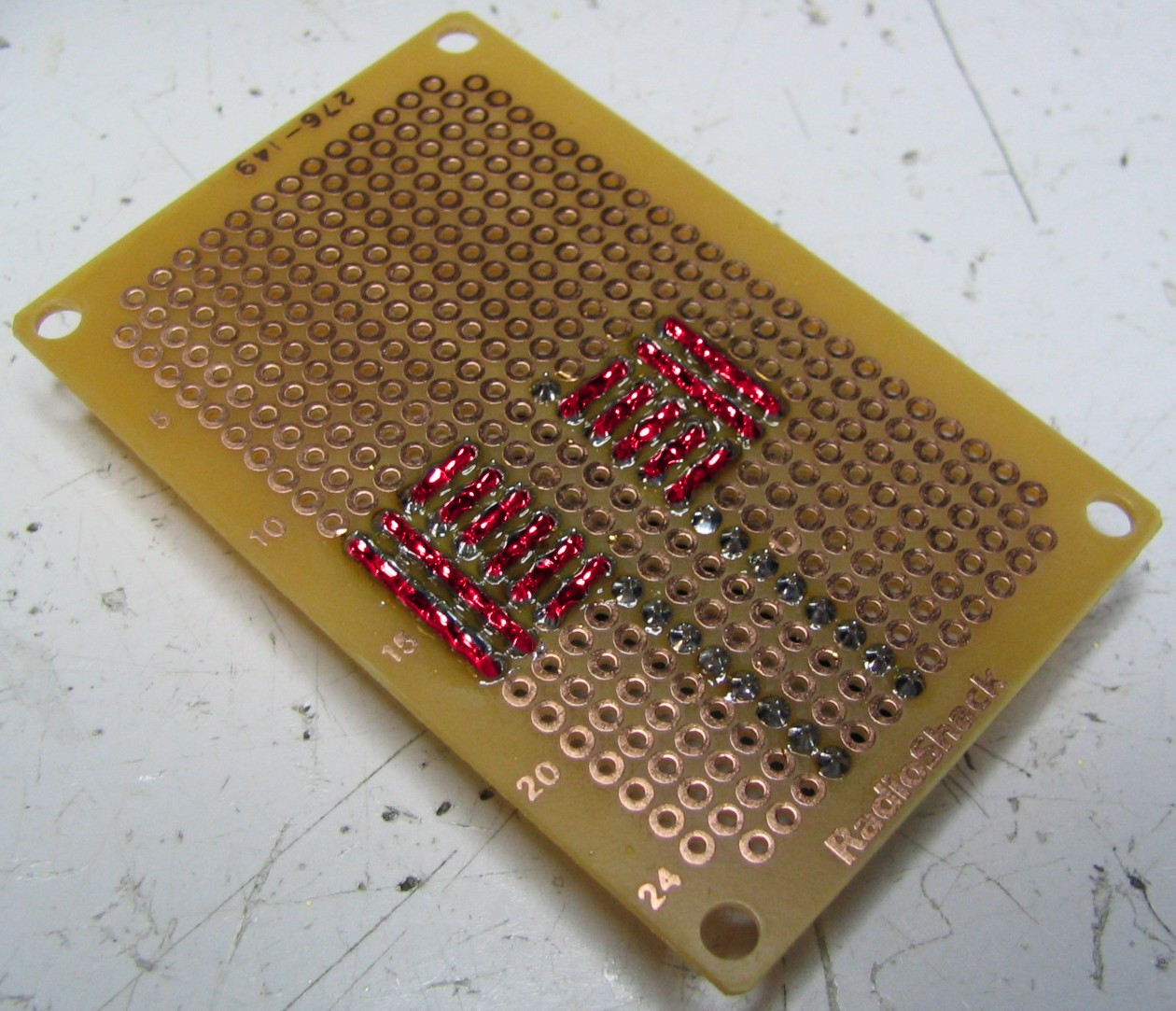 Next add two more rows of the 5 pin headers at the bottom right. Solder those in (pic not included). This will be for the ICSP connector of the programmer. Note that if you are using the more expensive programmer, you should check out this post concerning the different pinouts of the programmer. Now bend the leads on the resistor into perfect 90 degree angles.
 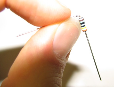 Add the resistor to the perf board, and bend the leads again as shown. Solder both leads, but DO NOT cut the leads! (not yet)
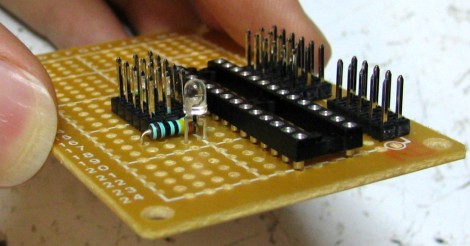
Now add the LED as shown, slightly above the board. Make sure the longer lead (+) of the polarized LED is on the side closer to the DIP socket. Solder it in, but DO NOT cut the leads! (not yet)
 Turn the board over, and solder as shown. Click the image for an enlarged close-up. Red represents wires, and blue represents a connection with a pin. Reference the schematic if unsure. Notice how I bent the LED wire and resistor wire to connect several pins together? You can also use normal wire, but I use this method out of laziness and l337-ness all rolled into one. Make sure the wire doesn't touch the copper padding.
 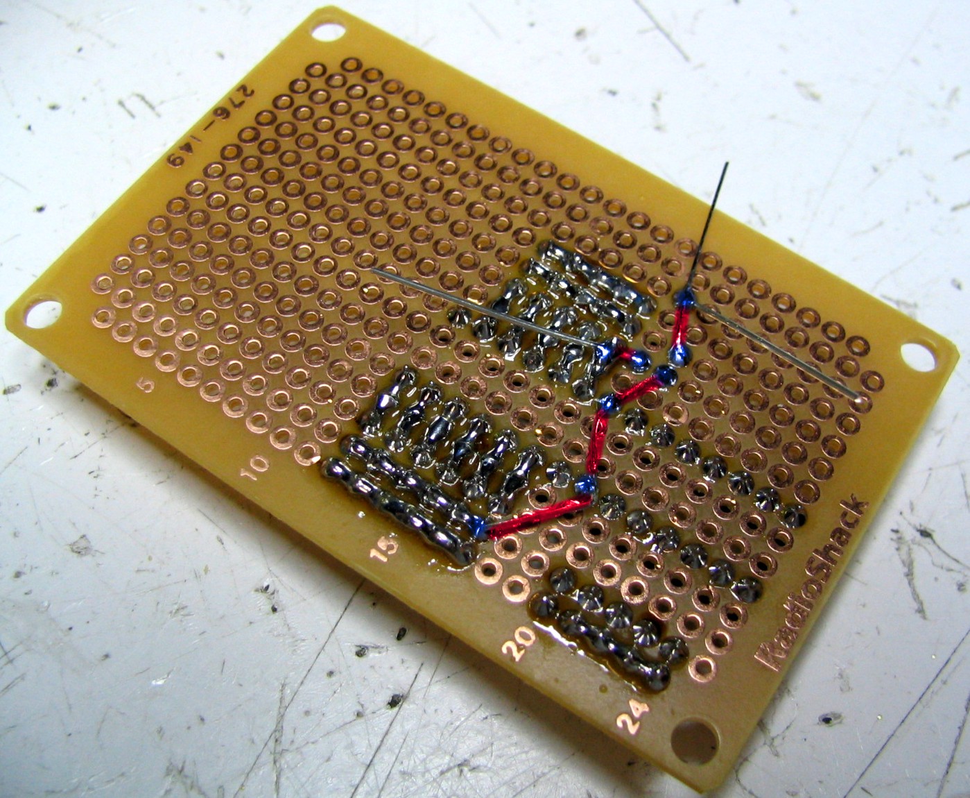 You may now trim the leads.
 Now we will connect all grounds together. I like to use black wire to represent ground because it can save me a lot of confusion if my wiring gets messy. Click the image if you need an enlarged close-up. The blue coloring represents connections.
 Relax, you are already half-way done!
 Add the big capacitor and solder the pins in. Make sure that the longer lead is on the side closest to the DIP socket. Notice the (-) sign on the capacitor? This is the negative side, which should have the shorter lead. This is important because the capacitor, just like the LED, is polarized and only works plugged in the right way. Make sure the capacitor negative lead is inline with the male header row farthest to the perf board edge. Check the schematic if unsure. (DO NOT CUT LEADS YET!)
 Add in the voltage regulator. Make sure you do it as shown! The middle pin of the regulator (ground) should be inline with the negative lead of the capacitor (ground). You may trim the three voltage regulator leads after soldering them in.
 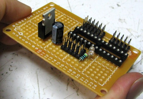 Now add the 3 pin header. If you are using the single cell batteries (ie 4.8V battery holder), you would not need this header. But if you are going to use a RC battery pack, you could plug it directly into this three pin header. DO NOT CUT THE LEADS YET! note: There is a minor mistake I made here that I want to point out. For the 3 pin header, shift it one hole over to the right (from holes CDE to DEF). Have it so the farthest left pin is connected to ground and the middle pin is connected to power.
 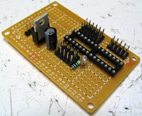 Now turn the board over and solder as shown. I bent the leads of the capacitor to use as connecting wires, but you can also make the connections using real wires. Be aware that these two wires will receive 100% of all current in your circuit - it could be several amps! Click the image to see an enlarged close-up (red for wires and blue for connections to pins).
 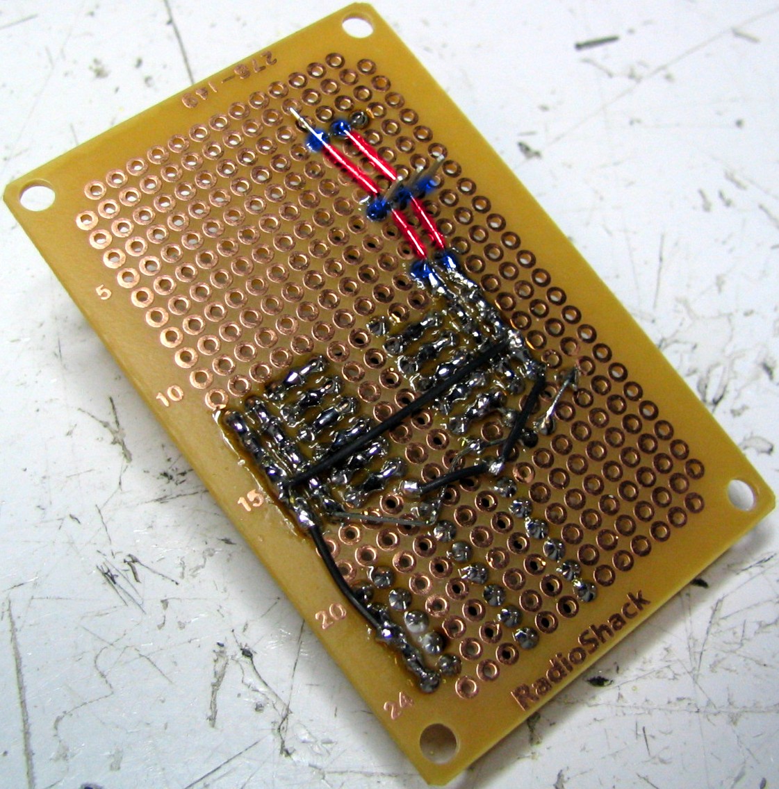 Note for those using the 4.8 battery holder: You want the power from the 9V only going to the electronics, and the power from your AA battery holder going only to the servos. They both share ground, but the + voltages are different and so shouldnt be connected. As such you need to make a small correction to the circuit. Please see this graphical representation. First, dont solder where the green X is. This seperates the two different power sources. Second, you want the large black capacitor to connect between ground and the servo power bus. Do not have it connected to the voltage regulator input pin. Third, attach the AA power and ground as shown in the graphical representation. If you are using a 6V battery pack, you can ignore this note.
 While you are at it, add in this purple wire. This wire will transfer the output 5V from your regulator to the middle row of the sensor power bus.

Now we want wire up the Programmer ICSP Header (see schematic). I used thin yellow wire for this, so as not to confuse with ground or 5V power. Click to enlarge.

Finally, we will add a ceramic capacitor (non-polarized) between pins AVCC and GND, and connect AVCC directly to AREF.
 Flipping it over, here is a close-up of the connections.
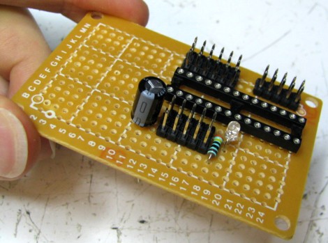
 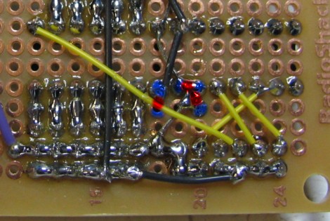 You are almost done (yaaaaay!)
If you don't have the proper testing equipment, plug in your battery pack and pray to the robot gods that your circuit doesn't melt in a pretty fire . . .The first test is called a connectivity test. Get out a multi-meter and do a connectivity test to make sure the pins that aren't supposed to be connected aren't connected. If by chance you accidentally bridged power and ground, your circuit could spark and your batteries melt. If you put the multi-meter on the resistance setting, make sure all non-connected pins have at least 5 kohm resistance or you may have power issues. You may need to get your soldering iron back out to fix any potential problems you find.
 Then do what I like to call a 'smoke test.' This is when you power up your circuit with a power supply. Plug your circuit in, start the voltage at 1V and work your way up slowly to 6.5V. The current draw should be under 50mA. If you see a huge current draw (or smoke), there is a mistake in your circuit so turn off power immediately. Otherwise, at 6.5V, get out your multi-meter again and check voltages on all the pins to make sure everything is working.
  The sensor bus should read 5V (as long as the input is greater than 6V), while the servo bus should equal your battery voltage.
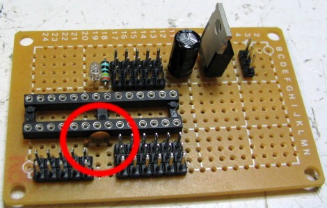
 Plug in the black ATmega8 IC (finally, eh?). Be careful of static electricity. You may also have to bend in the pins so that they all go in. Be patient while doing this. After the pins are in, push the IC into the socket carefully.
Plug in the battery. For the 6V battery pack, just plug it in to the 3 pin male header. Remember to verify that the black wire is going to ground and the red wire to power! I was dumb and didn't . . . but was also lucky that nothing fried (the regulator provides some reverse polarity protection, apparently). Check the schematic for reference.
 For the battery holder method at 4.8V: Solder in the black wire to ground and solder the red wire to the servo power bus. Check the modified schematic if you aren't sure.
  For the battery holder method at 4.8V: Then with a 9V battery, attach the - to ground and the + to the voltage regulator input. A good method is to remove a 9V battery connector from an old toy (or buy cheap from RadioShack) and directly solder the wires onto your perf board.
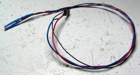
Now we will plug in the programmer. On the end of the programmer is the ICSP header (the black boxy thing). Look for a triangle on the front of it, as in this picture. This arrow marks pin 1.
 Plug in the header as shown. As always, if you aren't sure, check the schematic. The arrow side should be closest to the ATmega8 IC.
  To finish the connection, plug in the other end of the programmer into a serial port of your computer. If your PC does not have a serial port (such as my Dell laptop), you will need to buy a serial-to-USB adaptor cable (~$15, left cable in picture). Optionally, you may also want to buy a serial extension cable (~$5, right cable in picture).
 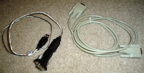 The extension cable is great if you want to keep your robot plugged in while it runs around (for sensor output by serial, etc).
 Your servo should have three colored wires: red goes to the + of your battery, black goes to - of your battery, and white (or sometimes yellow) goes to a digital output pin on your microcontroller (for the control signal). Again, if you would like to learn more about servos, check out the servo tutorial.
 And if you haven't figured it out yet already, plug your servos into PD0 and PD1 (pin 2 and pin 3). The black wire of the servo goes to the ground power bus (the one furthest away from the ATmega8).
 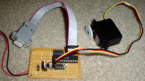 Congratulations, you now have functional robot brains! Yum!
 Now you must make two photoresistor sensors. Go to the photoresistor tutorialand follow the detailed instructions. I used a 1.5kohm resistor for R with the middle sized photoresistors in the RadioShack kit, but your situation might be different so you might want to recalculate your R value.
 You dont need to do the crimping method described to make this sensor, but its a more professional method and makes your sensor more modular (can be scrapped for future robots). The disadvantage to it is that the crimping tool can be a little expensive.
 Now attach your photoresistor sensors to the robot. I used packaging tape, but any method would work. Make sure the sensors are evenly spaced and at a decent angle. Later, when testing your robot, you will probably need to adjust the position of the sensors. I also tried poking holes into the bottle for the sensors to stick out of, but the sensors didn't stay put.
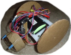
 Now plug your sensors into your circuit board, and mount your board onto your robot. Personally, I recommend using the four big holes in the perf board corners to screw your board into your robot. But I was lazy and just stuck it into the water bottle. The problem with this lazy method is that its difficult to attach your programming cable to your robot when the circuit board isn't mounted properly. I expect you to mount it properly =P
  You will probably have a huge jumble of wires sticking out above your robot. This is bad design because wires could jostle loose or get tangled on something. Get a twist-tie from a bag of bread and use it to tie the wires together, as shown in the above image. Your robot is almost complete! We just need to program it now . . .
0 comments:
Post a Comment